
ELF EVIDENCE SURFACES
Clifford E Carnicom
Nov 09 2002
Current research indicates the apparent or possible presence of ambient Extremely Low Frequency (ELF) signals that require identification as to their origin, purpose, informational content, intended target and effect upon the population. The current findings require the involvement of independent citizens and researchers for the purpose of validating or refuting the methods and measurements that are described on this page. The implications of such findings, if confirmed, would appear to be of a serious nature due to the direct linkage of ELF propagation and human mental functioning.
This page will serve primarily to describe the the method and technique that has been developed to investigate ELF detection; further research on this subject is now required. I am not a professional in the field of electromagnetic theory and application; my research is provided in good faith to address the serious consideration of ELF propagation in connection with the aerosol operations. This page also serves as repeated call to professionals in the fields of electrical engineering and electromagnetic propagation to critique, design and participate in methods of detection of ELF propagation. Considerable speculative discussion has emerged over the years between the potential linkage of the aerosol operations and the HAARP project and relevant technologies; such discussion is now deserving of more rigorous examination by the citizens of this nation. Many other professional disciplines share in their responsibility to address the concerns raised on this page, with a special emphasis upon the health profession. Those wishing to contribute to this effort at this level or to offer constructive advice are invited to contact me at cec101@usa.com
The heart and basis of this discussion involves the development of a resonant circuit operating at ELF frequencies. This project was begun in an exploratory fashion only, to learn about the nature of resonant circuits and their behavior. As an admitted accidental consequence of the investigation, the apparent detection of unexplained ELF propagation now requires further examination.
Readings have apparently been detected consistently over a several day period at approximately 2.5Hz, 16Hz, 21Hz and 30Hz. Power grid readings of 60Hz and the second harmonic at 120Hz have also been detected as a control mechanism for the process.
This section ends the summary findings of this work. The next section of this page will now relate the more technical aspects of this endeavor.
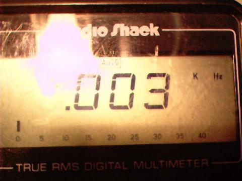
Detected ELF reading from developed resonant circuit : .003KHz (3Hz)
The basis of detection for this work is a resonant LC (inductive-capacitive) circuit. A resonant circuit for ELF frequencies has been constructed on the following premise:
In a LC circuit, resonance is achieved at a frequency of:
fr = 1 / (2 * pi * (L*C)1/2)
where fr is the resonant circuit frequency in Hz, L is the inductance of the circuit in Henries (H) and C is the capacitance in farads (F). The basis for development of the resonant frequency involves a condition of equality between inductive and capacitive reactance.
There are therefore numerous combinations of values of both L and C that can produce a resonant circuit. Certain restrictions exist on materials available on hand, however, and the following combination of components has been used in this effort:
C = 1 Farad ( approx.)
L = 3 * (4.03mH) = 12.09mH (approximate) (series of 3 inductors of approx. 4.03mH each)
A one farad capacitor is a rather unusual capacitor, and one of these high level capacitors had been acquired for earlier research on a separate topic. These capacitors are inexpensive (rated for 5V), and are apparently used in battery backup situations involving computers.
Several choices for unmarked coils were available, and the value of inductance was determined by the following method described by Donald L. Burdette (Reference : http://www.sxlist.com/techref/inductor/measure.htm)
“Someone recently asked how to measure inductance. Obviously, the best way is to have an inductance bridge or meter. But since I have neither, here’s my favorite way:
Get a sine wave oscillator, and put the inductor and a resistor in series across the output. I generally start with about 100 ohms. Adjust the oscillator frequency until the voltage across the inductor and the resistor is equal. Since they are 90 degrees out of phase, each will be 0.707 times the oscillator voltage. At this frequency, the inductor has an impedance of 100 ohms, and the inductance can be calculated from Z = 2 * pi * f * L.”
This method was applied to several available inductors until a suitable combination was developed. A series combination (additive for inductance) of three 4.0mH (approx.) coils was used. This combination leads to a resonant frequency estimate of:
fr = 1 / (2 * pi * (3 * 4.0E-3H * 1F)1/2)
fr = 1.5Hz (approx.) which is certainly in a desirable range of frequencies for this project.
In practice, it is found that the circuit is sensitive to resonance across a spectrum of approximately 1-150Hz, which is a function of the Q of the circuit. Traditional antenna structures for the reception of such frequencies are extraordinarily large (on the order of hundreds of feet), so at this point the circuit development was considered simply to be an exploratory venture. Early submarine communication projects in the northeast US involving ELF propagation involve antenna arrays of vast size, so expectations for any detection system were minimal at this stage of the research. It is certain that those knowledgeable in these affairs will be able to greatly improve upon the current research; the findings are presented simply as they have occurred.
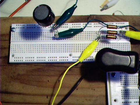
Photograph of ELF resonant LC circuit developed.
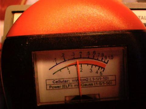
The object at right center is a magnetic sensor from a
Gauss EMF(Electromagnetic Field) meter.
This circuit was then investigated and evaluated with respect to an introduced sine wave at various frequencies. At this point, a serendipitous event appears to have occurred involving the use of a gauss EMF (electromagnetic field) meter that was also available from earlier research. The purpose of this meter is to detect small variations in the the magnetic field of the local environment. The meter is quite sensitive, and will show detectable variations down to a level of approximately 0.1 milligauss To give an example of a field strength that is detectable by a meter of this caliber, the median field strength of a group of digital electronic clocks measured at a distance of 46 inches is approximately 0.2milligauss(mG). For further examples of field strength values, please refer to the table presented at International Control Systems. Such meters for consumer use are available commercially at modest cost (approx. $40); the particular meter used is the Cell Sensor, designed also to measure power radiation from mobile telephones.
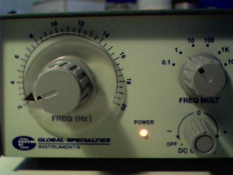
Sine wave generator used to introduce a signal into the circuit.
It was then noticed that whenever a sine wave of 60Hz was introduced into the circuit and the magnetic sensor of the gaussmeter was held in the vicinity of the inductors, that an oscillation of the needle of the gaussmeter became clearly visible. This oscillation was pronounced and the intensity was directly reactive to the injected frequency and the distance from the coils. To give an idea of the field strength from the 60Hz signal, the sensor held several inches away (8-12″) produced an oscillation of approximately 1.5mG on the meter. A distance less than this would overwhelm the sensitive scale on the meter, and control of readings is direct in relation to distance from the inductors. The oscillation was narrowly defined in terms of frequency input to the circuit; maximum variation occurred sharply within then range of 59 to 61Hz. It was by this time apparent that the power grid ELF waves were readily and easily detectable with the LC and gaussmeter circuit combination that had now developed. Oscillation of the gaussmeter needle would immediately cease upon departure from this specified frequency of 60Hz and the gaussmeter needle would become still. In essence, a sensitive ELF detector was now available, and the resonance of the original circuit designed was a critical factor in amplifying the ambient ELF signal (in this case from the power grid system).
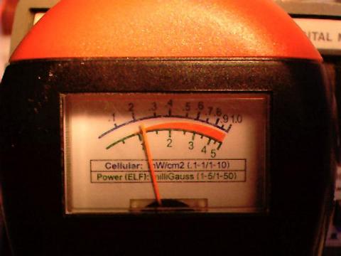
Photos which show stages of oscillation of the needle in response to a resonant frequency.
(1 of 2)
Photos which show stages of oscillation of the needle in response to a resonant frequency.
(2 of 2)
Explorations were then conducted across a much wider range of ELF frequencies. The next discovery was the detection of the second harmonic of the power grid system at 120Hz. Oscillation occurred at this frequency also, was easily detected, and could be increased in magnitude by placing the magnetic sensor closer to the set of inductor coils. Again the oscillation was restricted to a very narrow range of frequency (120Hz, +/- 1Hz) and it immediately decreased and ceased upon a departure from this frequency.
The particular function generator (sine wave) used permits frequencies to be introduced into the circuit of 0.2Hz to 200K Hz. Exploration was then extended to cover the broader range of frequencies permitted by this generator.
It was found that magnification of the needle movement was especially helpful in the detection of additional frequencies. Oscillation magnitudes of the the gaussmeter needle are on the order of 0.1 to 0.4mG for the lower ELF frequencies detected; careful observation under lighted magnification is required. Also it is found that the lower the frequency sought, the closer the magnetic sensor is to be placed near the inductor coils. This ranges from a fraction of an inch to approximately 1 foot distance over the range of frequencies examined. The power grid system creates an especially strong oscillation which is useful for control and calibration procedures.
Surprisingly, several additional lower ELF frequencies were subsequently determined through careful observation over a period of several days. Identical results have been found on each occasion of measurement, and the frequencies appear to remain constant. At this point I do not have an adequate explanation for the existence of these frequencies in the ambient environment, and it is to this purpose that I address this paper.
The ELF frequencies being detected within the limits of instrumentation currently available are:
2.5 to 2.6 Hz (best estimate)
15 -16 Hz
20- 21Hz
30 -31Hz
What appears to be a fundamental ELF signal at 2.5Hz is estimated to be accurate within +/- 0.5Hz. The remaining ELF signals are estimated to be accurate within +/- 1Hz. It is reasonable, within the limits of instrumentation available, to consider the higher signals as potential harmonics (6, 8,12?) of the detected fundamental of 2.5 – 2.6 Hz. The 15-16Hz signal is observed to be weaker within the group.
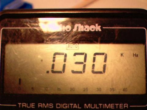
Detected ELF reading from developed resonant circuit : .003KHz (3Hz)
It is reaffirmed that there now exists a need to explore, investigate and explain the ELF frequencies that appear to be under detection. The first stage of this process is to seek corroboration from independent citizens and researchers as to the validity or failings of the findings reported here. Depending upon the results of those efforts, and if such findings are verified, the accountability of these signals as to origin, purpose, information content, target and effect becomes an absolute necessity.
This paper will be revised, edited or corrected as is appropriate.
Clifford E Carnicom
Nov 09 2002
