
INTRODUCING A MAGNETOMETER
Clifford E Carnicom
Oct 31 2002
This page will describe the construction of a relatively simple magnetometer, a device which is useful to detect local variations in the earth’s magnetic field. Results of any data collection and analysis will not be discussed at this time, and they are to be reserved for separate presentation. The photographs are hopefully fairly self-explanatory in guiding the construction of the unit. A variation of several degrees in the magnetic field is known to occur at mid-latitudes of the earth during periods of severe geomagnetic storms. The unit shown can be measured to approximately 1/8 degree (approx. 7.5 minutes of arc) and is therefore sufficient to detect fairly small variations in the local magnetic field activity. The basis for development of this magnetometer is extracted from Electronic Sensor Circuits and Projects, by Forrest M. Mims III, 2000. Note that no electronics or power supply is required for the operation of this magnetometer. Modifications can be made to the plans shown as long as the essential functions are provided for.
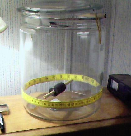
Photograph of the Magnetometer, showing glass housing unit,
suspended dowel with 10 ring magnets, and graduated scale.
A glass storage container approximately 10″ high and approximately 9.25″ diameter is used to house the sensor. This particular storage container was located within the canning section of a local department store. A dowel of 3/8 inch diameter is acquired for use as the pointer frame. Ten ring magnets were purchased from the local electronics shop, each of which has a interior hole of approximately 3/8 inch diameter as well. The outside diameter of the magnets used is approximately 1 inch.
The dowel is cut to approximately 8 1/4 inches, or such that it will easily rotate when suspended within the glass jar. Allowance of approximately 1/2 inch must also be made to accommodate a pointer mechanism which is attached to the dowel. The final dimension of the dowel, with the pointer attached, will allow approximately 1/16 inch clearance from the inside walls of the glass jar – just enough to allow for free rotation of the magnets and dowel assembly.
The magnets will slide easily onto the center region of the suspended dowel.
A pointer is also constructed to allow for fine readings of the graduated tape scale which is attached to the outside circumference of the glass jar. The pointer used is constructed from a sharp pointed toothpick. A small diameter hole is drilled into one end of the dowel, and the end of a sharp pointed toothpick is broken off and inserted into the drilled hole in the center of one end of the dowel. It is found that blackening the extreme tip of the pointer (toothpick segment) with a black felt pen will greatly aid the measurement process. See the second and third photographs of this page for a depiction of the pointer unit.
The dowel is suspended by a fine thread which is tied to the dowel at each end of the magnet group. The supporting structure for the dowel is another segment of dowel which spans the diameter of the glass storage unit at the top. The dowel at the top of glass jar can be adjusted in small increments to allow for proper centering of the suspended dowel and magnet combination within the jar. Adjustment in this case is provided for with rubber bands attached to the side of jar with tape and an encircling thread; this combination provides enough tension to place the suspended dowel in the exact center of the glass jar. Other arrangements for arranging the suspension can surely suffice.
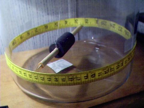
Photograph of the suspended dowel, pointer unit, dowel, magnets and graduated scale.
A cloth sewing tape is used for the graduated scale. In the case shown, approximately 740mm of cloth tape have been used to span the circumference of the glass jar. Positioning of the cloth measuring tape is critical to the accurate reading of the scale. In the case shown, each millimeter on the scale corresponds to approximately .486 (360 degrees / 740 mm) degrees of arc deflection in the northerly horizontal component of the local magnetic field. Absolute measurements are of little value in use of this meter, and emphasis should be placed upon relative changes. The point of origin for readings on the meter is arbitrary; anywhere on the scale will suffice. The only requirement for use of the meter is to record the pointer on the scale to the nearest .25mm, or in other words, the nearest one-quarter mark on the cloth scale. This can be easily accomplished with the use of a magnifying glass under adequate lighting. The unit is to be placed in a stable, undisturbed location away from any air currents.
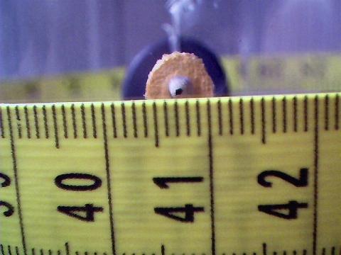
Close up of pointer scale from the perspective of measurement.
Notice the blackened tip of the pointer assists greatly with measurement.
Each mark represents 1mm of arc distance on the circumference of the glass jar.
The reading shown is taken as 407.25. A magnifying glass
will greatly aid in the measurement process.
Readings taken thus far range from approximately 398 to 410, or a span of 12 marks on the scale shown. This corresponds to a maximum deflection range of approximately 5.8 degrees of arc, which represents significant and detectable variability in the earth’s local magnetic field.
Readers are encouraged to construct a similar or improved magnetometer at their location and to begin collecting data that will be used to correlate any variations in magnetic field activity with the onset of the aerosol operations. As mentioned earlier, analysis of data under collection will be presented in a separate section. Users may wish to refer to the data set under collection since Oct 07, 2002 at the page entitled Predict the Operations : Sunspots and Humidity available within this site.

