
ATMOSPHERIC CONDUCTIVITY II
Clifford E Carnicom
Santa Fe, NM
May 07 2003
A method to estimate the conductivity of the lower atmosphere has been established. This method relies upon the use of a Van de Graaf generator of a rated voltage capacity, along with the measurement of the maximum spark length gap that can be achieved. Results from this method indicate an increase in the conductivity of the lower atmosphere by a factor of approximately 3 to 20. This model, if accepted, supports the claim that the fundamental electrical nature of the atmosphere has been altered as a result of the aerosol operations that continue to be conducted without informed consent.
An initial paper on this subject, entitled Atmospheric Conductivity, was presented in July 2001; the conclusions of that paper remain valid to this day. The benefit of the current study is that it provides an estimate as to the magnitude of the change in atmospheric conductivity using relatively simple methods and equipment.
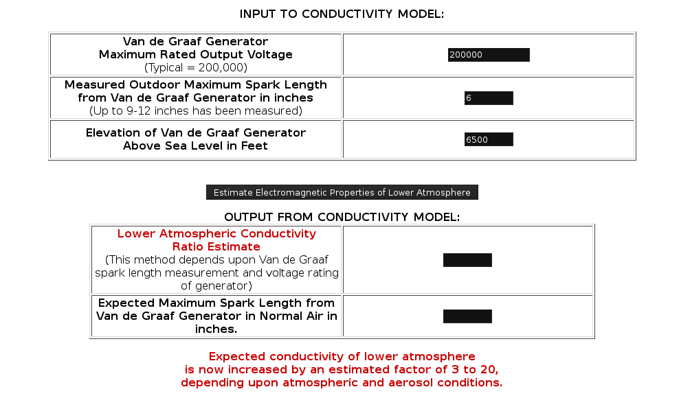
A calculator version of this estimate is provided below. The model attempts to predict the ratio of increase in conductivity relative to the expected value of a normal atmosphere. The required input into the model is the rating of the Van de Graaf generator in volts, the maximum measured spark length in inches and the elevation of the station above sea level. Additional estimated electromagnetic properties of the lower atmosphere under variable conditions are also available (continued below).
Click Here for JavaScript Applet
Expected conductivity of lower atmosphere
is now increased by an estimated factor of 3 to 20,
depending upon atmospheric and aerosol conditions.
Considerable testing has been conducted in both indoor and outdoor environments. The unusual nature of the outdoor environment was first brought to light with the initial paper of July 2001 that has been mentioned, where a spark length that exceeded any theoretical estimate was measured on several occasions. That difference has since become even more readily visible with the addition of an indoor air filter.
An ionizing indoor air filter has now been in operation for approximately 6 months at this location. This particular filter is manufactured by Flair (EPA Est. Reg. No. 065975-TN-001). One of the claims of this ionizing filter is that it attempts to duplicate the natural environment positive to negative ion ratio, as it emits both positive and negative ions. From earlier research, that ratio has been stated to be approximately 250 to 200 in the lower atmosphere. This particular filter by claim does not emit negative ions only. Ionizers that generate negative ions exclusively may create their own complications by increasing particulate adherence to walls and surfaces. This problem does not arise with this model, and regular cleaning of the floor appears to adequately collect the settled particulates. By spark length measurement indications, this filter does appear to be operating as is claimed, as the measured spark length in the indoor environment consistently agrees extremely well with the theoretical value. For the 200,000 volt generator that is being used, this expected spark gap is on the order of 3 inches. Such a measurement in this indoor environment is being achieved repeatedly with little variation. Incidentally, the ozone generator on this filter is not being used as observations indicate that it may have a negative impact upon some plant species. I have no commercial interest in this filter.
The outdoor environment and measured spark lengths are an entirely different matter. Spark lengths being measured outdoors commonly exceed the theoretical value for this Van de Graaf generator. Maximum spark lengths of 5-6 inches are achieved on a daily basis; on certain occasions the spark length has approached values of 9 to 12 inches. By the conductivity estimates above, this would appear to be most unexpected unless the dielectric strength of the air (insulating capability) has been decreased. Conversely, the significant increase in the measured outdoor spark length does indicate an increase in the conductivity level of the lower atmosphere. Additionally, the outdoor spark gap measurements more often elicit a pronounced leader structure; this would seem to indicate the existence of multiple paths for ionization.
The advantage of the method that has been developed is that it provides an estimate for the conductivity change in the atmosphere as a function of only the rated voltage of the Van de Graaf generator, the measured spark length under breakdown conditions and the elevation of the measurement station.
Any changes to this paper will be made as is appropriate.
Clifford E Carnicom
May 07 2003
Additional Notes 05/12/03:
Extremely heavy aerosol operations occurred over the Santa Fe NM area on May 12, 2003. Spark lengths of 6 to 9 inches were measured during the early evening of this same day, accordingly. The correlation of maximum spark length with increased electron density continues to be studied.
The rationale for the method developed is as follows:
The conductivity of a gas based upon the classical free electron model is1,2:
(1) sigma =( ne * e2 * tau) / m
where
e is the charge of an electron : -1.6E-19 coulombs,
m is the mass of an electron : 9.11E-31kg,
ne is the density of electrons per m3
and tau is the collision rate expressed as the number of collisions per second, and sigma is the conductivity in siemens (ohm-1).
Two difficulties are faced with the use of this equation; estimates for both ne and tau are not necessarily simple to determine or to measure.
It is possible to proceed, however, with the following additional relations that are available3,4:
(2) tau = L / vrms
where vrms is the root mean square velocity of the electrons in the gas and L is the mean free path between electron collisions.
and vrms is given by5:
(3) vrms = ( ( 3 * k * T ) / m )1/2
where k is Boltzmann’s constant : 1.38E-23 J / K, and T is the temperature of the gas in degrees Kelvin.
Also, we have available for consideration6:
(4) Ebmax = Wion / e * L
where Ebmax is the breakdown voltage (Dielectric Strength) of Normal Air : = 3E6 Volts/meter
and Wion is the work of ionization of the atmosphere : = 5E-18 J (~30eV).
And finally, we can include7:
Ebmax = Vbmax / dmeas
where Vbmax = the maximum voltage rating of the electrode sphere (Van de Graaf generator) and dmeas is the measured spark length in meters corresponding to the breakdown voltage of the surrounding gas (air).
Let us proceed to see if a more usable expression for the conductivity of the atmosphere based upon the measured spark length can be developed.
We now have by substitution for tau:
sigma = ( ne * e2 * L ) / ( vrms * m )
and by further substitution for L, the mean free path:
sigma = ( ne * e2 * Wion ) / ( Ebmax * e * vrms * m)
and by further substitution for Ebmax:
sigma = ( ne * e2 * Wion * dmeas ) / ( Vbmax * e * vrms * m)
or
sigma = ( ne * e * Wion * dmeas ) / ( Vbmax * vrms * m)
This expression now has the advantage that it introduces the measured spark length into the eventual determination of an estimate for the conductivity of the air. Unfortunately, this equation retains the disadvantage of n, the electron density term. Determination of the electron density is a difficult problem without specialized equipment and procedures; ionosonde theory is relevant in that case.
Let us see if we can begin to address the difficulty with the electron density term.
From a theoretical discussion, we have the following differential equation which models the formation of electrons under breakdown voltage conditions as related to lightning formation8,9:
dnx = alpha * nx * dx
where nx represents the number of electrons moving through a plane at x, and alpha is a coefficient (Townsend ionization coefficient) that represents the number of new electrons created per unit distance by a drifting electron. The solution to this equation is:
nx = no * expalpha * x
where no is the initial electron density of the medium. This solutions informs us that electrons increase in an exponential format during the process of ionization and breakdown (lightning or Van de Graaf spark). This is referred to as a avalanche condition.
To solve for the number of electrons along a path (spark length), we shall solve this equation with respect to the limits of integration from 0 to dmeas, the measured spark length:
nx (totalmeas) = ( no * expalpha * dmeas) – ( no * exp0 )
or
nx (totalmeas) = no * ( expalpha*dmeas – 1 )
Similarly, for the theoretical spark length, we have:
nx (totalcalc) = no * ( expalpha*dcalc – 1 )
Now, we still have the difficulty of the estimate for the initial electron density, no. This will be circumvented to the necessary degree by looking at the ratios of conductivity from an altered to the normal environment, instead of the actual magnitude of the conductivity. In addition, there remains the difficulty of determining alpha, the Townsend ionization coefficient.
Let us proceed with a method to determine the Townsend coefficient. From this same theoretical discussion on lightning discharge, we have the following data provided for the Townsend coefficient:
|
volts / m – torr |
m – torr |
|
5000 |
6 |
|
10000 |
50 |
|
35000 |
500 |
A satisfactory least squares model for this data can be developed into the following form:
alpha* = 4.6E-8 * ( E / p )2.22
where alpha* is our first estimate for the Townsend coefficient as a function of the electric field strength to pressure ratio.
Now let us develop this coefficient further by allowing the pressure of the gas (elevation of observation) to become a variable:
A suitable differential model for atmospheric pressure as a function of elevation above sea level is available as10:
dp / dh = –.00004p
and a solution to this equation exists in the form:
p = 762 * exp-.00004h
where p is the pressure in torr, and h is the elevation above sea level in feet.
This leads us to an estimate for the Townsend coefficient as:
alpha = 4.6E-8 * ( Ebmax / ( 762 * exp-.00004h ) )
where the breakdown strength of the atmosphere is used as the electric field strength under spark gap conditions.
We now conclude the development by looking at the conductivity ratio estimate of a modified to a theoretical gas environment:
sigmameas ( no * ( expalpha*dmeas – 1 ) * e * Wion * dmeas ) / ( Vbmax * vrms * m)
_________ = ___________________________________________________________
sigmacalc ( no * ( expalpha*dcalc – 1 ) * e * Wion * dcalc ) / ( Vbmax * vrms * m)
where alpha is as defined above.
This can be simplified to:
sigmameas ( expalpha*dmeas – 1 ) * dmeas
_________ = _______________________
sigmacalc ( expalpha*dcalc – 1 ) * dcalc )
which is the final expression for the conductivity ratio as it is used within this paper.
1. Michael Mansfield, Understanding Physics, (Wiley and Sons, 1998), 622.
2. ecjones.org, Ionospheric Physics of Radio Wave Propagation, (http://ecjones.org/physics.html)
3. Mansfield, 622.
4. ecjones.org.
5. Mansfield, 288.
6. Niels Jonassen, Breakdown, Compliance Engineering, www.ce-mag.com/archive/01/01/MrStatic.html, (eq. 4).
7. Jonassen, (eq. 10).
8. Martin A. Ulman, Lightning, (Dover, 1984), 204-206.
9. George Joos, Theoretical Physics, (Dover, 1986), 434.
10. Claude Irwin Palmer, Practical Calculus for Home Study, (McGraw-Hill Book Company, 1924), 151.
